
Schematic diagram depicting typical truss bridge components (source: Historic American Engineering Record (HAER))
3 d8 m2 M3 i0 }$ ~1 L; L
Truss bridges are characterized by the joining of numerous relatively small structural members into a series of interconnected triangles. They were first built of wood, then iron, then steel or, occasionally, a combination of the materials. Many wooden truss bridges served North Carolina’s roads in the 19th and early 20th centuries. Only one still survives largely intact, the 1895 Bunker Hill Bridge near Claremont in Catawba County, which no longer carries traffic and is not part of the highway system. All of the state’s other truss bridges are metal structures, which partook of an explosion of design and technological innovations that began in the mid-19th century.
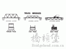
Basic truss bridge types found in North Carolina (source: HAER)
8 \6 D* @# R$ C+ l4 q2 ?A truss bridge can be characterized by the location of its traffic deck. At a pony truss, the travel surface passes along the bottom chords of trusses standing to either side that are not connected to each other at the top. These trusses are designed for lighter loads. At a through truss bridge, the deck again is carried along the bottom chord, but the trusses to either side are generally higher and are connected by cross-bracing at their tops. Designed for heavier loads and longer spans, this truss is the most common in North Carolina. The least common truss in the state is the deck truss, which carries its deck and traffic entirely on top of the truss structure.
Metal trusses may also be differentiated by how their structural members are connected. The earliest examples in the state were connected with pins. The pin connection was subsequently replaced by bolted and then welded connections.
There are numerous wood and metal truss types. The wooden Bunker Hill Bridge is a Haupt truss, a type invented in 1839. North Carolina’s metal truss bridges utilize only about five of the many types or subtypes of metal truss bridges—the Pratt, the Warren, the Parker, the Camelback, and the Pennsylvania.
 : X$ a8 H) X$ D
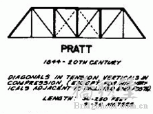
Pratt truss diagram (source: HAER)
普拉特桁式
The Pratt truss is identified by a simple web arrangement of diagonals in tension and verticals in compression. Patented in 1844 by engineer Thomas Pratt and his architect father, Caleb, the Pratt offered ease of design and fabrication by using economical, standard, rolled-angle and channel sections, plates, bars, rods, and I beams. Pratt trusses were dominant during the last quarter of the 19th century and continued in use well into the 20th. Most of the later examples of the truss used riveted or bolted rather than pinned connections. A larger number of intact Pratt trusses survived in North Carolina into the beginning of the 21st century than any other type.
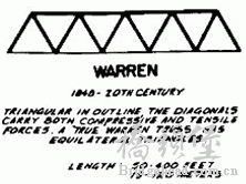
, I& W' w- l& `; C& OWarren truss diagram (source: HAER)
( i- a' a$ e2 A e3 S% j
华伦桁式
% o: Z4 h M) B: N/ r, cThe Warren truss design is distinguished by equal-sized members and the ability of some of the diagonals to act in both tension and compression. The type is generally characterized by thick, prominent, diagonal members, although verticals could be added for increased stiffness. Warren truss bridges gained popularity after 1900, as American engineers began to see the structural advantages of riveted or bolted connections over those that were pinned. The design was well suited to a variety of highway bridge applications and was very popular in North Carolina and nationally from about 1900 to 1930.
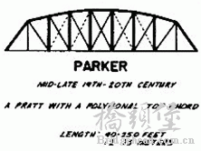
8 m& w4 q" ]5 r% G$ xParker truss diagram (source: HAER)
: M: u h$ c# J
派克桁式
5 T) M l4 d* lA Parker truss is a Pratt truss that has a polygonal top chord. It is named after engineer C. H. Parker, who is associated with the development of the design in the mid-19th century. Polygonal top chords offer savings in material and place the greatest depth of the truss at the center of the span where it is most needed. The riveted Parker truss was admirably suited for relatively long spans and it remained popular through the early decades of the 20th century.
 8 A9 }: @9 ^" c6 o0 S: P% {
Camelback truss diagram
(source: HAER)
$ F+ W# L4 p0 m% W# y+ C
驼背桁式) M- M; I8 N7 [+ e0 L4 x" H5 `( M
A Camelback truss is a variation of the Parker truss that has a polygonal upper chord of exactly five slopes. This provides some saving of material with the greatest depth of truss where it is most required, at the center of the span. The State Highway Commission—which made only limited use of the type and then only at long crossings—used the Camelback variant as the center span of Nash County Bridge 271, which it erected over the Tar River just east of Spring Hope in 1921.
 / H( ~6 M: v5 N
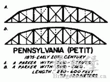
Pennsylvania truss diagram (source: HAER)
宾夕法尼亚桁式
The Pennsylvania truss is named after the Pennsylvania Railroad, whose engineers developed the design in 1875. It is yet another variant of the Pratt truss with polygonal top chords and panels that are additionally subdivided by ties and struts. The sloping of the top chords saves materials and best places the depths of the truss at the center of the span, while the subdivided panels distribute the loads uniformly and handle secondary stresses well. The Pennsylvania truss was well-suited to long spans and remained popular through the early decades of the 20th century. The state utilized it at a few crossings in the mid-1950s, reflecting a conservative application of truss technology by the Highway Commission.